






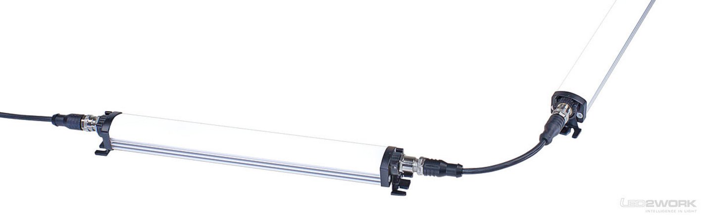
What does cascading mean?
Cascading describes the practice of wiring several industrial LED luminaires visually as a chain — the second luminaire hangs from the output of the first, the third from the output of the second, and so on. It saves circuits, reduces wiring effort and is standard practice in machine building.
Looks like a series connection — but it isn't. Electrically all luminaires sit in parallel on the same supply voltage. This distinction is the source of most planning errors.
Parallel rather than series — the key point
In a true series connection the voltage would be split per luminaire — 24 V ÷ 4 luminaires = 6 V each, which would immediately overload the driver. In cascading, every luminaire receives the full supply voltage; currents add up on the feed line.
In practice: with four 24 V luminaires drawing 1 A each, the power supply output must be able to deliver 4 A, and the feed line must carry that summed current. A single M12 cable (typical 4 A load limit) is then at its limit.
Benefits and limits of cascading
Benefits:
- One feed line instead of N circuits — fewer terminals in the cabinet
- Standard M12 wiring — no custom dimensions, no field terminations
- Switchable as a group — one signal line controls all luminaires
- Quick expansion — add a luminaire without running a new circuit
Limits and risks:
- Voltage drop on a long feed line — at 24 V it becomes critical; from 5 % below nominal the driver may regulate down
- Connector current rating — M12 is not designed for 8 A or more; for many luminaires a junction box or special topology is needed
- Inrush current — all drivers charge simultaneously; the startup peak is N times higher than for a single luminaire; the supply must cope
- One luminaire failing does not break the chain (parallel!) — good for availability, but fault diagnosis becomes harder
Planning rules in practice
- Maximum sum current of the chain: sum of all luminaire currents + 20 % margin, must stay below connector/cable limit.
- Calculate voltage drop: U_drop = I_sum × R_cable × length × 2. At 24 V applications U_drop should stay below 1 V.
- Driver inrush current: ask the manufacturer, multiply by number of luminaires, size the supply accordingly.
- Individual fuse per branch for more than 6 luminaires — prevents a single driver short from bringing down the whole system.
- Diagnosis via IO-Link-capable luminaires — individual status feedback per luminaire to the PLC; otherwise troubleshooting turns into guesswork.